Millipore BioPharmaceutical Division
SafePass® Sterile Transfer System
MILLIPORE
Publication XXXXXXXXX
Millipore BioPharmaceutical Division
SafePass® Sterile Transfer System
MILLIPORE
Publication XXXXXXXXX
Topics in this Manual
Table Of Contents
Operating Sequence at a Glance
Transfer Interface Operational Procedures
Sanitize Mode - Level 1 & Level 2
Returning a System to Millipore
Replacing the Sterilizing Source
Cycle On/Off DI – Door Interlock
Cycle On/Off HI – Handle Interlock
PLC and Development Software Information
Development Software Information
Products Ordered in the U.S. for Shipment Overseas:
Products Ordered in Countries Other Than the U.S.:
It is the responsibility of the purchaser to ensure that all employees who will operate and/or be near the SafePass® Sterile Transfer System are aware of the following cautionary items.
CAUTION
Never operate this equipment without proper training from a Millipore representative.
Ultra-violet lamps can cause serious eye damage; never operate this system without proper U.V. filtering eye protection.
Never operate this system without proper guarding in place.
Never operate this equipment if any of the safety features are defective.
Never Access any electrical control cabinets without first isolating the main power supply at the source. Only suitable, qualified people should undertake maintenance or electrical checks on this equipment.
Never operate this equipment if the utility pressures are below the specified requirements shown in this document.
Never force any operating part which may appear to be jammed, as operator injury may occur.
Never operate this equipment outside the manufacturers recommendations or outside the guidelines shown in the operation and maintenance manual.
It is the responsibility of the purchaser to ensure that the Sterile Transfer System is set up and programmed for the desired processing option.
If there is any doubt about operating the equipment safely, discontinue use and contact your Millipore representative immediately.
The SafePass® Sterile Transfer System is designed for use in a Class 100,000 clean area as defined by Federal Standard 209. Operating the system in a lower classification environment may cause significant equipment damage.
Never weld, drill or create gross particulate on or around the Sterile Transfer System, or significant equipment damage may occur.
Please ensure that you have read the manual and that you have been trained by a qualified Millipore representative before attempting to operate the SafePass® system. In particular, one should be aware of the safety precautions outlined in the previous chapter. (See Operator and Equipment Safety on page 11).
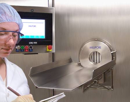
The SafePass Sterile Transfer System provides fast, easy and reliable transfer of sterile components or liquids into pharmaceutical filling environments including new or existing barrier isolators and clean-rooms. The SafePass System is designed for use in closed systems, for high-speed aseptic filling applications such as vaccines, and for manufacturing applications such as high-value biopharmaceutical products.
Unlike RTP (Rapid Transfer Port) systems, the patented UV sterilization process of the SafePass System assures a true sterile condition at the point of transfer in only 3 minutes. A highly reliable locking mechanism with a fail-safe alarm and lock-out system provides notification of events affecting sterilization and prevents premature opening of the port.
UV sterilization provides a true sterile transfer interface, sterilizing all surfaces of the docking collar that may have been exposed during docking, creating a sterile interface to the barrier and eliminating the ring of concern associated with RTP (Rapid Transfer Port) systems. The SafePass Sterile Transfer System has been qualified to achieve a 106 log reduction in less than 180 seconds on a range of organisms, including Bacillus subtilis ATCC® 6633, Bacillus pumilus ATCC 27142 and Bacillus stearothermophilus ATCC 7953.
Fast throughput is achieved as a result of the 3 minute sterilization cycle-time, fast enough to easily feed high speed lines running at 300 fills/min.
The sterile transfer containers are low cost, single use and fully disposable. They are equipped with a docking collar and protective overcap. The containers are available in a wide range of sizes and a variety of materials. These containers may be filled and sterilized on or off site and are suited for sterilization by gamma irradiation or ethylene oxide sterilization (ETOH).
Locking of the sterile transfer containers to the SafePass docking port requires no twisting. Simply insert the container collar into the port and lock in place using the locking handles. The SafePass transfer containers eliminate the cumbersome installation associated with canisters. For more information on the Sterile Transfer Containers and other system components, see the chapter titled Equipment Description on page 17.
The SafePass Sterile Transfer System Validation Package contains comprehensive protocols written to the same standards as the protocols used to validate pharmaceutical processes. The Validation Package provides the required documentation and procedures to support FAT (Factory Acceptance Testing), IQ (Installation Qualification) and OQ (Operation Qualification). Additionally, Millipore Specialists can provide onsite support to expedite validation.
Docking Port
The Docking Port is available in100 mm or 150 mm diameters. The Docking Port and lock mechanism are constructed of 316L Stainless Steel. For specifics on this area of the system, see the section titled Docking Port on page 18.
Operator Control System
The Operator Control System is comprised of the following items
· A PLC controller, either Siemens or Allen Bradley (Specified at time of purchase)
· A touch-screen operator interface. (See the section titled Touch Screen on page 21 for more information on this component).
· A print-out for each transfer cycle.
For detailed information on the Operator Control System and the SafePass® system software, see the section titled Control System Overview on page 29.
Sterilization Source
The Sterilization Source is comprised of quartz glass lenses, and UV lamps with an intensity of 8mW/cm2. They are rated to a minimum of 3000 cycles and operate at a wavelength of 254 nm. They are designed for quick disconnect and ease of replacement.
The SafePass Sterile Transfer System is comprised of several primary elements, as shown in Figure 1 below. In this chapter we will give a brief description of each in turn.
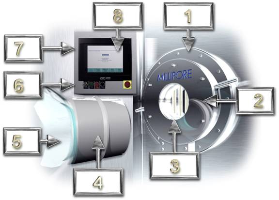
Figure 1: System Description
|
Key |
Item Represented |
See Page |
|
1 |
Transfer Interface |
pg.18 |
|
2 |
Docking Port |
pg.18 |
|
3 |
Sterilizing Source |
pg.18 |
|
4 |
Interface Collar |
pg.19 |
|
5 |
Sterile Transfer Container |
pg.19 |
|
6 |
Hardware Buttons |
pg.20 |
|
7 |
Control Panel |
pg.20 |
|
8 |
Touch Screen |
pg.21 |
The Transfer Interface consists of the Docking Port and the Sterilizing Source. It is the element that is attached permanently to the barrier or isolator wall between the non-sterile and the sterile area.
The Docking Port is provided with a 3 point clamping mechanism, which secures the Sterile Transfer Container directly in front of the Sterilizing Source. When the Interface Collar of the Sterile Transfer Container is docked to the Docking Port, a sequential sterilizing cycle is undertaken to create a sterile connection between the non-sterile and the sterile area. The Docking Port is equipped with interlocks preventing component transfer if the correct sterilizing sequence parameters have not been met.
The Sterilizing Source is very compact and is fully contained within the footprint of the Transfer Interface. The Sterilizing Source is comprised of a number of UV lamps positioned over reflectors (the number of lamps in the Sterilizing Source depends on the diameter of the Interface Collar). The 150mm system contains 9 lamps.
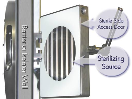
Figure 2: Sterilizing Source
The Interface Collar creates the primary connection between the non-sterile and the sterile area. The Interface Collar is a single piece injection molded component, with a single use tear off panel, which is sterilized by the Sterilizing Source. The design of the Interface Collar is key to providing a low cost disposable system. To minimize the potential bio-burden on the interface collar, it is fitted with an Interface Collar Protection Cap. The cap is held in place until just before docking by means of an air tight seal. The seal and cap are removed just prior to sterilization and transfer.
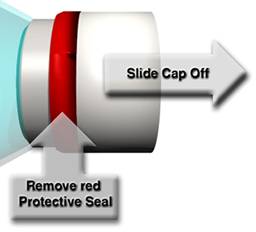
Figure 3: Interface Collar with cap and protective seal.
The Sterile Transfer Container is a low cost, single use, disposable unit that contains the sterile components to be transferred. The Container can be charged with non-sterile components for sterilization within the Container prior to transfer, or the Container can be pre sterilized and filled with sterile components for transfer. See Figure 4 and Figure 5 for examples.

Figure 4: Sterile Transfer Container
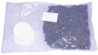
Figure 5: Sterile Transfer Container
Note: The SafePass® System is designed for use ONLY with SafePass® Sterile Transfer Containers. Attempted use of any other type of container will void the product warranty, and may damage the system.
The Control Panel is the area in which all functions of SafePass® are monitored and/or executed. It is comprised of a touch screen interface from which the software aspects of the system are controlled, and several hardware buttons at the base.
Figure 6: Control Panel
The Hardware Buttons are located at the base of the Control Panel. These include the Power On/Off switch (Lockable), the Start Button, the Done Button and the Reset Button. (see Figure 7).
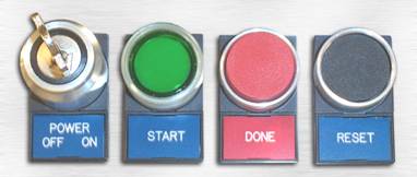
Figure 7: Hardware Buttons
The SafePass Sterile Transfer System is available with the following electrical requirements.
115, 240 and 460 Volts / 47 – 63 Hertz
80 - 90 psi / 2 SCFM
This chapter contains a brief description of the operating sequence for the SafePass® system. Although the SafePass® performs many steps in the course of a single sterilizing cycle, the following sections will break the cycle down into the seven steps that an operator must know. Each of the seven steps will first be outlined in brief, and later explained in more detail.
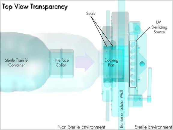
Figure 8: System at a Glance
1. Remove the protective overcap from the docking collar of the Sterile Transfer container.
2. Insert the docking collar into the SafePass docking port and lock into position.
3. Initiate the UV sterilization cycle at the touchscreen operator interface.
4. When the cycle is complete, open the access door on the sterile side through the access glove port and remove the sealed panel from the docking collar using the supplied tool.
5. Transfer the sterile components through the Docking Port into the sterile environment.
6. Close and lock the inner access door.
7. Remove and discard the used sterile transfer container. The system is now ready for the next transfer.
We will now cover each step in detail.
To remove the protective overcap from the docking collar, simply remove the red seal from around the cap and pull the cap straight off. See Figure 9 for details.
IMPORTANT - Do not remove the tear away panel at this time
Figure 9: Removing the protective seal and overcap
To insert and lock the docking collar into the SafePass docking port, gently push it into place. There should be no resistance. If there is, make sure that there is no obstruction and that the Docking Collar is not damaged. Once the Docking Collar is in place, turn the locking handles clockwise until they reach the stops. See Figure 10 for details.
Figure 10: Inserting the Interface collar into the docking port
To initiate the cycle at the interface, push the Cycle Start button on the Control Panel.
This assumes that the operator is properly logged into the system. If you need help on this subject, see the section titled “Log On” on page 34 of this manual. If you would like to see a detailed chain of events showing what the hardware and software do during a cycle, see the section titled “Starting a Sterilizing Cycle” on page 47 of this manual.
Open the Access Door on the sterile side. To open the access door, simply lift the locking handle and swing the door inward. This exposes the sealed panel on the docking collar. You will need to use the supplied tool to remove the lid from the collar. See Figure 11 for details.
Note: The system will not allow the door to be opened unless the sterilizing cycle is complete. The message, “Sterilization is completed, Open the door”, will appear on the interface.
Figure 11: Removing the Panel from the Interface Collar
To transfer the sterile components through the Docking Port, one may either lift the container and effectively pour the contents through, or one can reach through and remove items at leisure.
To close and lock the door, push the door firmly closed, and then rotate the locking handle until it stops. If the door is properly locked, this will be reflected on the Operator Control Interface.
Note: Before closing and locking the door, it is a good idea to see if there is anything such as trash or refuse that should be removed from the sterile environment. These items may be put into the container for disposal on the non-sterile side. This includes the tear away panel that was removed to access the container. Simply fold it in half, and it will fit through.
To remove the used sterile transfer container, simply rotate the locking handles counter clockwise until they reach the stops. The container can be safely removed, and discarded along with any refuse that it contains. This is the reverse of what is shown in step 2 and Figure 10.
The system is now ready for the next transfer.
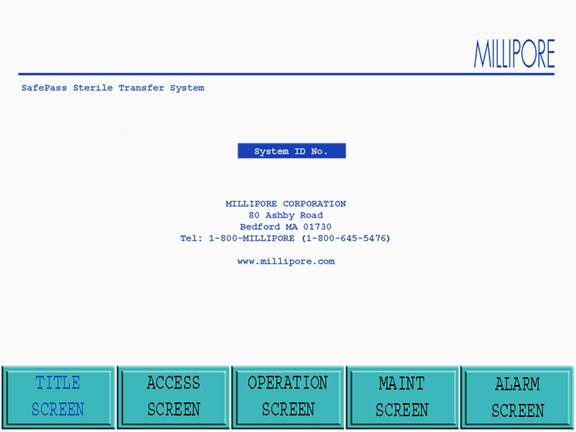
Figure 12: Title Screen
The Title screen is Accessed when the Title screen icon at the base of the active screen is touched or when the Sterile Transfer System is activated. The following goto icons are displayed at the base of the Title screen:
· Access screen
· Operation screen
· Maintenance screen
· Alarm screen
From this screen the operator may only enter the Access screen if the power was just applied at the POWER ON key switch (no password is required to enter the Access screen). No other screen may be Accessed. The goto icons will be blocked. If the operator Accessed the Title screen from another operational screen, the operator may re enter the previous screen or Access any other screens their password level permits.
The goto icons not available to particular password levels will be blocked. If the system is operational when the operator is in the Title screen and an alarm event occurs, the system will automatically return the operator to the Operation screen.
Note: Access to the desired screen can be made by touching the goto icon for that screen at the bottom of the Title screen.

Figure 13: Access Screen
The Access screen is entered when the Access screen icon at the base of the active screen is touched. If the power was just applied at the POWER ON key switch the operator must enter the Access screen to Log On , thus allowing operation of the system. In the Access screen a flag will be displayed noting one of the following messages:
· System Non-Sterile (Red Background)
· System Sterile (Green Background)
· Source Cycles Left
· Starter Cycles Left
· Seal Cycles Left
Note: The messages are automatically generated by outputs from the Barrier / Isolation System and are used by the Transfer Interface to prevent the incorrect operation. In the Access screen the following information windows are provided to allow the operator view the remaining cycles (active life) for the following:
The following two sections summarize operator log on and system Access from the Access screen for each of the two Access levels in the Transfer Interface PLC:
In the Access screen, the level 2 operators must Log On to allow system use. The level 2 operator who is permitted Access can go to the following screens:
· Title screen:
· Operation screen
· Alarm screen
If the Sterile flag is displayed, the level 2 operator is permitted Access to enter a batch number by touching the Batch # icon in the Access screen. If the level 2 operator does not enter a batch number, Access to the Operation screen will not be permitted.
If the Non-Sterile flag is displayed, the level 2 operator will be prevented from entering a batch number into the Transfer Interface. The level 2 operator must prepare the Transfer Interface for sterilization with the barrier isolation system. The goto icon for the Operation screen will be replaced with a Sanitize Mode goto icon. Once the Sanitize Cycle is completed (including receiving the ready signal from the barrier), the level 2 operator may enter a batch number by touching the Batch # icon.
At the end of the operation of the Transfer Interface, the operator enters the Access screen to log off by touching the Log Off icon.
In the Access screen the level 1 supervisor must Log On to allow system use. goto icons will allow Access to the following screens of the Transfer Interface to the level 1 supervisor who is permitted Access (in addition to the Access screen):
· Title screen
· Operation screen
· Maintenance screen
· Alarm screen
If the Sterile flag is displayed, the level 1 supervisor is permitted Access to enter a batch number by touching the Batch # icon in the Access screen. If the level 1 supervisor does not enter a batch number, Access to the Operation screen will not be permitted.
If the Non-Sterile flag is displayed the level 1 supervisor will be prevented from entering a batch number into the Transfer Interface. The level 1 supervisor must prepare the Transfer Interface for sterilization with the barrier isolation system. The goto icon for the Operation screen will be replaced with a SANITIZE MODE screen goto icon. Once the Sanitize Cycle is completed (including receiving the ready signal from the barrier), the level 1 operator may enter a batch number by touching the Batch # icon.
· At the end of the operation of the Transfer Interface the supervisor enters the Access screen to log off by touching the Log Off icon.
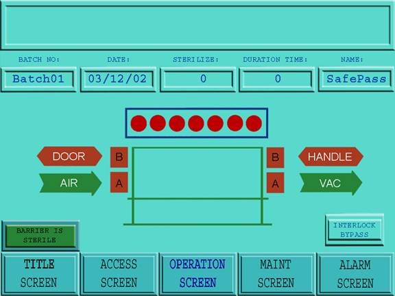
Figure 14: Operation Screen
The Operation screen is Accessed when the Operation screen icon at the base of the active screen is touched. Once Accessed (by the level 2 operator or level 1 supervisor) the Operation screen controls the Transfer Interface for component transfer. All functions are undertaken automatically by the Transfer Interface PLC, with the exception of the following:
· Cycle Start
· Cycle Done
· Reset (Alarms After they Have been Corrected)
The following information is displayed on top of the Operation screen:
· Batch No. (which is generated automatically when the operator enters the batch number in the Access screen).
· Date (which is generated automatically when the operator enters the batch number in the Access screen).
· Sterilize (the seconds are displayed in reverse for the current sterilizing cycle).
· Duration Time (the number of minutes and seconds is displayed as a reverse countdown before the next sterilizing cycle can begin).
· Name (which is generated automatically when the operator logs on).
In addition to the above, an Alarm window provides a summary of the last alarm events.
To start a sterilizing cycle, the operator pushes the Cycle Start button. When the transfer of components has been completed, the operator closes the door and pushes the Cycle Done button. The information shown in the following section is printed out automatically (or saved to a disk ) at the end of the sterilizing cycle.
The top of the page provides a header bar noting the Sterile Transfer System Serial number. Before the batch data is printed out, the alarm list associated with that batch will be printed out. The following data is then recorded:
· Date
· Time
· Barrier / Isolator (Sterile or Non-Sterile)
· Source Serial number
· Starter Serial number
· Seal Serial number
· Sterilizing Cycles Completed
· Operators Name
· Batch Number
· Seal A Pressure – Pass or Fail
· Seal B Pressure – Pass or Fail
· Vacuum – Pass or Fail
· Sterilization Duration – (In Seconds)
· Lamps Operational – (0-9)
A screen graphic in the Operation screen will highlight the status of the Transfer Interface during operation.
If an alarm event occurs while the operator is in the Operation screen, the alarm will be displayed in the Alarm window within the Operation screen. All alarms will terminate a sterilizing cycle other than the following (once the respective alarm has been reset):
· 25 Sterilizing Source Sterilizing Cycles Remaining
· Starter Set 100 Cycles Remaining
· Seal Set 100 Cycles Remaining
At the base of the Operation screen, goto icons will allow Access (password level permitting) to the following screens of the Transfer Interface:
· Title screen
· Access screen
· Maintenance screen
· Alarm screen
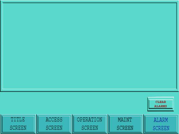
Figure 15: Alarm Screen
The Alarm screen is Accessed when the Alarm screen icon at the base of the active screen is touched.
When an alarm message is displayed in the alarm message window of the Operation screen, the operator must Access the Alarm screen. In the Alarm screen the operator must correct the fault associated with the alarm (which is highlighted at the top of the alarm event log).
At the base of the Operation screen, goto icons will allow Access (password level permitting) to the following screens of the Transfer Interface:
· Title screen
· Access screen
· Operation screen
· Maintenance screen
Note: Regardless of the screen Accessed, if an alarm occurs during operation the operator interface will default to the Operation screen.
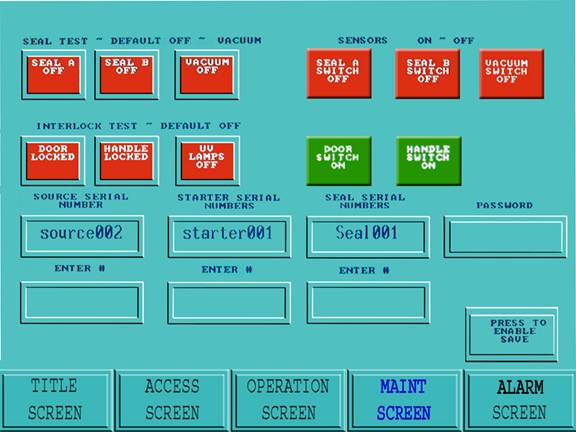
Figure 16: Maintenance Screen
The Maintenance screen is Accessed when the Maintenance screen icon at the base of the active screen is touched. The Maintenance screen Access is limited to level 1 supervisor.
In the Maintenance screen the following sub systems can be cycled (switched on or off).
· Lamps – On / Off
· Seal Set A – Inflate / Deflate
· Seal Set B – Inflate / Deflate
· Door Interlock – On / Off
· Handle Interlock – On / Off
· Collar Interlock – On / Off
In the Maintenance screen, the following sub system changes can be implemented (items that can be changed or replaced):
· Sterilizing Source Change Over
· Starter Set Change Over
· Seal Set Change Over
· Operator Password Changes
In the Maintenance screen, the following windows are provided to allow the operator to view currently active items:
· Sterilizing Source Change Over
· Starter Set Change Over
· Seal Set Change Over
At the base of the Maintenance screen, icons allow Access (password level permitting) to the following screens of the Transfer Interface:
· Title screen
· Access screen
· Operation screen
· Maintenance screen
Operator and supervisor levels can gain Access to the operation of the Transfer Interface by undertaking the following steps:
8. Touch the Log On icon located in the Access screen. (A screen appears with an alphanumeric keypad and a space for password to be entered.
9. Type in the password and touch Enter . The password will be entered and the Access screen will return.
10. If the password is correct, Access will be permitted to the system at the appropriate level (see Table 1). If the password is incorrect, Access to the system will be denied.
11. If Log On fails, repeat steps 1-3.
|
Function |
Level 1 |
Level 2 |
|
Title screen |
Yes |
Yes |
|
Access screen |
Yes |
Yes |
|
Operation screen |
Yes |
Yes |
|
Alarm screen |
Yes |
Yes |
|
Maintenance screen |
Yes |
No |
Table 1: Password Access Levels
To allow operation of the transfer interface, the batch number is entered as follows:
12. Touch the Batch Number icon in the Access screen.
13. A screen is displayed with an alphanumeric keypad and a space for a batch number to be entered.
14. Enter the desired batch number (it will be displayed in the Batch # window on the Access screen) and touch Enter . The Access screen will return.
15. If the batch number is correct, touch the Press to Save Batch Number icon; the batch number will be saved.
16. If the batch number is incorrect, repeat steps 1 to 4.
IMPORTANT: For level 1 and 2 Access where the Barrier / Isolator is Sterile, and a batch number is entered, the following should be noted:
The operator may change the batch number at any time. The batch number entered at that time will be printed out with each sterilizing cycle. There are no interlocks preventing the batch number from being changed mid-process or from entering an incorrect batch number.
IMPORTANT: For correct operation, the level 2 Access procedures should always be followed when using the Transfer Interface. Including:
- Log On
- Sanitize Mode (If Required)
- Batch Number (New or Check Existing)
If the flag at the top of the Access screen displays Non-Sterile (this signal is received from the Barrier / Isolator), the following steps must be undertaken by level 2 Access before a batch number can be entered to allow the operation of the Transfer Interface:
1. Touch the Sanitize Mode icon (this icon is actually the Operation screen goto icon which has been blocked out until the barrier / isolator has been sterilized).
2. The Transfer Interface automatically displays the Operation screen (which is used to effect the Sanitize Mode .
3. Insert the blanking plug into the Docking Port and close the docking handles.
4. The graphic labeled HANDLE goes from green to red.
5. The interface graphic goes from red to green.
6. Touch the Cycle Start button.
7. The sterilizing lamps will engage, and the sterilize counter will begin to operate. Once the sterilizing time is complete, the message, SANITIZE MODE OPEN THE DOOR is displayed on the graphic.
8. Open the Transfer Interface door. If the door is not opened within a certain time window, the alarm will activate.
9. When the door is completely opened, a proximity switch is triggered. The message DOOR IS OPENED READY FOR SANITIZATION, is displayed on the mimic screen.
10. While the door is open, a signal is sent to the barrier from the transfer system indicating that the system is ready for a sanitization cycle to begin.
11. Sanitize the barrier with the door opened.
12. When the Barrier / Isolator Sterile signal is received from the Barrier / Isolator System, the message BARRIER IS SANITIZED, is displayed on the graphic.
13. Close the Transfer interface door and touch the Cycle Done button.
14. Once the docking handles are unlocked and the blanking plug is removed, the Access screen will be automatically displayed as the active screen. The Sanitize Mode icon will change to the Operation screen goto icon. Access to the Operation screen will result in an alarm, until a batch # has been entered.
IMPORTANT: There is no printout for the Sanitizing Mode.
Note: When the sterility of the Barrier / Isolator system is broken it will send a signal to the transfer interface to display the message, Non-Sterile.
1. The operator inserts the Interface Collar of the sterile transfer Container into the Docking Port of the transfer interface.
2. The Interface Collar on the mimic screen turns from red to green (automatically) to show that the Interface Collar is correctly inserted.
3. If the Interface Collar remains red it is not correctly seated. The operator must reposition the Interface Collar in the Docking Port until it is correctly seated.
1. The operator rotates the locking handle to secure the Interface Collar to the transfer interface. The locking handles are locked in position automatically.
2. The Interface Collar on the mimic screen turns from red to green to show that the docking handles are closed.
3. The graphic marked HANDLE turns from green to red, showing that the handle is locked.
Note: If the docking handle is engaged before the Interface Collar is correctly seated, the handle interlock can be released by touching the Interlock Bypass icon on the operation screen.
Depress the Cycle Start Button on the control panel.
The Seal A on the mimic screen turns from red to green to show that it has inflated.
Note: If Seal A fails to inflate or the seal pressure is incorrect, Seal A on the mimic screen will remain red and an alarm will appear at the top of the Operation screen.
Note: If compressed air is working correctly the compressed air flag on the mimic screen will be green. If there is a compressed air fault the compressed air flag on the mimic screen will turn red and an alarm will appear at the top of the Operation screen.
When Vacuum is activated between the static seals and Seal A, the vacuum line on the mimic panel turns from red to green to show that it has activated.
Note: If the vacuum fails to activate or if the interstitial space between Seal A and static seals fails to hold a vacuum, the vacuum line remains red on the mimic screen and an alarm will appear at the top of the Operation screen.
The Sterilizing Source activates and the circular lamps of the Sterilizing Source turn from red to dark blue to show that the lamps have activated.
Note: If any of the lamps fail to activate or the lamp is operating outside the preset parameters the affected lamp remains red on the mimic screen and an alarm will appear at the top of the Operation screen.
The Seal B on the mimic screen turns from red to green to show that it has inflated.
Note: If Seal B fails to inflate or the seal pressure is incorrect, Seal B on the mimic screen will remain red and an alarm will appear at the top of the Operation screen.
At the end of the sterilizing cycle the Sterilizing Source is deactivated. The PLC then verifies the following conditions:
· Pressure in Seal A was correct for the sterilizing cycle.
· Pressure in Seal B was correct for the sterilizing cycle.
· Each lamp was verified as active and been active for the correct period of time for each of the primary and secondary seal sterilization cycles.
· The preset parameters for each lamp verified as within the preset window.
· Vacuum was maintained throughout the sterilizing cycle.
Note: If any item was operating incorrectly the subject part of the mimic panel will remain red and an alarm will appear at the top of the Operation screen.
If all items are verified as correct, the message, STERILIZATION IS COMPLETED OPEN THE DOOR, will be displayed on the Transfer Interface. At this time, the graphic representing the door turns from red to green, thus signaling the operator to open the transfer door.
Once the operator opens the transfer interface door, the message DOOR IS OPEN TRANSFER COMPONENTS, will be displayed on the Transfer Interface.
The operator then removes the pull-tab and Accesses the contents of the Sterile Transfer Container.
Note: When the door is opened the PLC verifies that a vacuum is maintained in the interstitial space between Seals A and B. If vacuum is not present an alarm will appear at the top of the Operation screen.
Note: If vacuum air is working correctly the vacuum flag on the mimic screen will turn to green. If there is a vacuum fault the vacuum flag on the mimic screen will remain red and an alarm will appear at the top of the Operation screen.
When the Sterile Transfer Container has been emptied, the operator places any waste generated back into the Sterile Transfer Container.
Note: If the transfer is not completed within 15 minutes of the Interface Collar being sterilized the Transfer Interface door will not open and a time out alarm will appear in the Alarm window. The operator must reset the system as follows:
· Release the docking handles by touching the Interlock Bypass icon on the operation screen.
· Remove the Interface Collar.
· Reset the alarm
· Reposition the Interface Collar
· Repeat the Sterilizing Cycle.
Once the operator completes the transfer, and closes the transfer interface door, the message DOOR IS CLOSED PRESS Done PB will be displayed on the transfer interface.
The operator closes the door and presses the Done button. The door latch interlock on the sterile side is engaged automatically, and the handle interlock on the non-sterile side disengages automatically.
The operator opens the handle on the non-sterile side and removes the empty Container from the port.
Note: If the door interlock on the sterile side fails to engage, the door simulation on the Operation screen will remain open and an alarm will appear on screen.
Note: If an alarm event occurs while the operator is in the Operation screen the operator must touch the Alarm Goto icon at the bottom of the screen to clear the alarm event before being permitted to proceed with system operation.
When the sterilizing cycle is completed the following information is printed out automatically:
The top of the page is provided with a header bar noting the Sterile Transfer System Serial number. Before the batch data is printed out, the alarm list associated with that batch will be printed out in the following sequence;
· Date
· Time
· Barrier / Isolator (Sterile or Non-Sterile)
· Source Serial #
· Starter Serial #
· Seal Serial #
· Sterilizing Cycles Completed
· Operators Name
· Batch Number
· Seal A Pressure – Pass or Fail
· Seal B Pressure – Pass or Fail
· Vacuum – Pass or Fail
· Sterilization Duration – (In Seconds)
· Lamps Operational – (0-7)
At the end of a batch:
1. Enter the Access screen (either operator or supervisor).
2. Touch the Batch Number icon in the Access screen. A screen is displayed with an alphanumeric keypad and a space for a batch number to be entered.
3. Enter 0 as the batch number. This will log off the existing batch.
4. Touch the Press to Save Batch Number icon twice; the previous batch number will be terminated.
When the active operator logs off, the Transfer Interface will not permit further interface until a new operator logs on. The current operators name (i.e., the operator logged on) will be printed out with each sterilizing cycle while that operator remains logged on.
1. Touch the Log Off icon. A screen is displayed with an alphanumeric keypad and a space for a password to be entered (the screen may be moved to the top or the bottom of the operator interface using the Ý or ß keys on the keypad).
2. Touch 0 and press Enter. The operator will be logged out and the Access screen will return.
3. If the entry is accepted, the operator or supervisor will be logged off the system.
4. If Log Off failed, repeat steps 1-3.
The following control functions and indicators are provided on the control panel of the Sterile Transfer System (in addition to the mute button):
· Power On/Off Key Switch
· Cycle Start Button
· Done Button
· Reset Button
The Power On/Off Key Switch will activate the mains power to the Sterile Transfer System. Alarm data and historical data contained in the PLC of the Sterile Transfer System will remain unaffected when the main power is switched off.
The Cycle Start Button is used to start the Sterile Transfer System sterilizing sequence (the button will be illuminated when there is power on to the system.
The Cycle Done Button is used to end the Sterile Transfer System sterilizing sequence.
The operator corrects a fault and uses the Reset Button to inactivate the alarm.
To help you get the best performance from your Millipore products, the Technical Support staff is available to provide prompt, reliable assistance. Before calling for assistance, know the software version and system serial number for the SafePass® system (see Contacting Millipore on page 79) for contact information. You may also contact your local Millipore applications specialist for help.
· Contact Millipore Technical Service to obtain a Return Authorization number and instructions.
·
Package the SafePass® system in its original
container.
If you do not have the original container, Millipore can provide a replacement.
Ship the product to the Millipore address that is provided by your Millipore
Technical Service Representative.
Caution: Never ship the system without an authorized Millipore container. Doing so will void the product warranty.
The parts which require routine replacements are the sterilizing source, starter sets and seal sets. It is a good idea to have replacements on hand. Other spares and kits are listed as well. All of the spare parts and catalogue numbers are NOT listed here. If you require a part that is not listed below, please contact your local Millipore representative ( see the section titled Contacting Millipore on page 79 for more information).
Table 2: Spare Parts and Accessories
|
Part Name / Description |
Catalog Number |
|
|
|
|
|
|
|
|
|
|
|
|
|
|
|
|
|
|
|
|
|
|
|
|
|
|
|
|
|
|
|
|
|
|
|
|
|
|
|
|
|
|
|
|
|
|
|
|
|
|
|
|
|
|
|
|
|
|
|
|
|
|
|
Note: The list shown above is not a complete list of spare parts available. Should you require parts not listed here, please contact your Millipore representative.
The Maintenance screen is Accessed when the Maintenance screen Icon at the base of the active screen is touched. The Maintenance screen Access is limited to level 1 supervisors.
Important: When a level 1 supervisor logs on, Access is permitted to all elements of the Transfer Interface. Level 1 Access removes all internal interlocks and allows the operation of the Transfer Interface in a way which could affect the sterility of the Barrier / Isolator. It is also possible to activate the UV Lamps with the Sterilizing Source in the open position or when there is no interface collar present. Care must be take to prevent exposure of eyes to the rays of the UV Lamps as the can blind in a very short duration.
The following information is displayed at the bottom of the Operation screen (these are not active Icons and are displayed for information only):
· Source Serial # Displays the serial number for the currently active Sterilizing Source.
· Starter Serial # Displays the serial number for the currently active Starter Set.
· Seal Serial # Displays the serial number for the currently active Seal Set.
In the Maintenance screen the following Icons are provided to allow cycling of individual systems:
· UV Lamps - Allows the UV lamps to be turned On & Off.
· SA - Allows Seal A to be Inflated / Deflated.
· SB - Allows Seal B to be Inflated / Deflated.
· Door - Allows the Door Interlock to be Activated / Deactivated.
· Handle - Allows the Handle Interlock to be Activated / Deactivated.
· Source # – Allows the Sterilizing Source change to be recorded in the PLC.
· Starter # – Allows the Starter change to be recorded in the PLC.
· Seal # – Allows the Seal change to be recorded in the PLC.
· Password – Allows the password level and assignments to be changed.
When the installed Sterilizing Source has reached the end of its service life (i.e., after 3,000 sterilizing cycles), it must be replaced. Service requirement is automatically notified by the Transfer Interface by an alarm message when only 25 sterilizing cycles remain. The remaining number of cycles for the currently installed Sterilizing Source is displayed in the Access screen.
Important: Once these 25 cycles have been used, the Transfer Interface will cease further operation. A new Sterilizing Source must be attached to allow further operation.
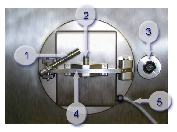
Figure 17: Key parts of SafePass®(sterile side)
1. Door Handle 2. Locking Pin 3. Quick Connect 4. Swing Arm 5. Power Cord
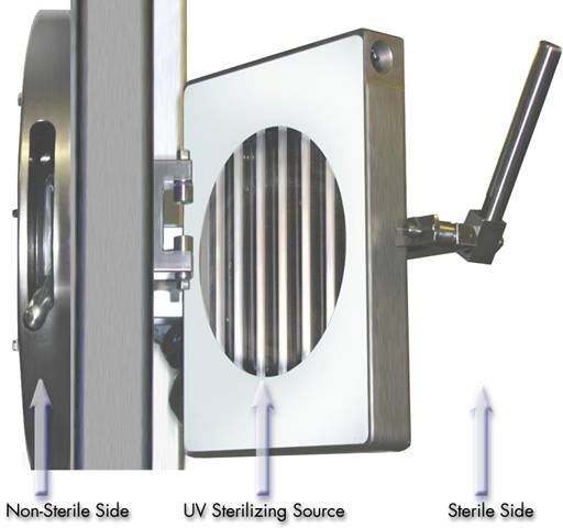
Figure 18: UV Source terms identification
To replace the Sterilizing Source the supervisor must undertake the following steps:
Remove the old sterilizing source from the sterile transfer system.
· Shut off power from the main cabinet. Be sure to lock out the cabinet.
· Disconnect the power cord from the isolator to the light source (quick disconnect).
· With the door open, remove the locking pin from the swing arm.
· Remove the sterilizing source from the isolator.
· Dispose of as necessary.
Install the new sterilizing source onto the sterile transfer system.
· Place the sterilizing source on the swing arm.
· Insert the locking pin.
· Connect the power cord (which is connected to the sterilizing source) to the to the quick connect power source.
· Turn on power at the main cabinet.
· Turn on power to the system.
· Log on at supervisor level.
· Go to the maintenance screen.
· Touch the Source # Icon.
· A screen is displayed with an alphanumeric keypad and a space for a source number to be entered (the screen may be moved to the top or the bottom of the operator interface using the Ý or ß keys on the keypad).
· Enter the serial number which is stamped on the hinge bracket of the Sterilizing Source (it will be displayed in the Source # window on the Access screen) and touch Enter. The Access screen will return.
· If the serial number is correct, touch the Press To Save Icon; the batch number will be saved to a second Source # window.
· If the serial number is incorrect, repeat steps 2 to 5.
Important: Each time the serial number is changed using steps 2 to 5 above the counter for the Sterilizing Source will reset to 3000. This will also occur if the serial number is changed for a partially used Sterilizing Source or a totally used Sterilizing Source. The maximum recommended life of the Sterilizing Source is 3,000 cycles. After this point the Sterilizing Source must be changed to allow the system to function correctly.
When the installed Starter Sets have reached the end of their service life (i.e., after 10,000 sterilizing cycles) they are replaced. Replacement required is automatically notified by the Transfer Interface by an alarm message when only 100 sterilizing cycles for the installed Starter Set remains. The remaining number of cycles for the currently installed Starter Set is displayed in the Access screen.
Important: Once these 100 cycles have been used, the Transfer Interface will cease further operation. A new Starter Set must be installed to allow further operation.
The Starter units appear as shown in Figure 19 and Figure 20.
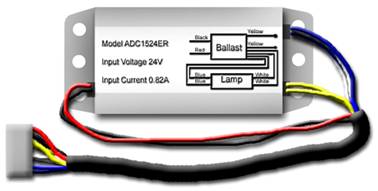
Figure 19: Single Starter Unit with quick disconnect plug
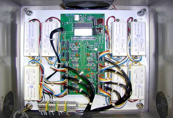
Figure 20: View inside of Panel showing 7 Starter units properly configured
To replace the Starter Set the supervisor must undertake the following steps:
· Shut off power from the main cabinet. Be sure to lock out the cabinet.
· Open the panel to access the starters.
· Unplug the quick disconnects from the circuit board.
· Remove the starters from the panel.
· Install the new set of starters into the panel. (Be sure to keep the old and new starters separated. It is a good idea to mark the old units with an indelible marker prior to removing them, so that they are easily identified as unusable.)
· Plug in the quick connects to the circuit board.
· Close the panel before returning power to the main cabinet.
· Restore power to the system.
· Log on at supervisor level.
· Go to the maintenance screen.
· Touch the Start # icon.
· A screen is displayed with an alphanumeric keypad and a space for a Start number to be entered (the screen may be moved to the top or the bottom of the operator interface using the Ý or ß keys on the keypad).
· Enter the serial number which is assigned to the new set of starters (it will be displayed in the Start # window on the Access screen) and touch Enter. The Access screen will return.
· If the serial number is correct, touch the Press To Save Icon the batch number will be saved to a second Start # window.
· If the serial number is incorrect, repeat steps 2 to 5.
Important: Each time the serial number is changed using steps 2 to 5 above the counter for Starter Set will reset to 10,000, and count down with each cycle spent. This will also occur if the serial number is changed for a partially used Starter Set or a totally used Starter Set. The maximum recommended life of the Starter Set is 10,000 cycles. After this point the Starter Set must be changed to allow the system to function correctly.
Important: The Starter Sets for the Transfer Interface are matched. To allow the system to function correctly only use the complete Starter Set provided. Do not mix starters from different sets.
When the installed Seal Sets have reached the end of their service life (i.e., after 10,000 sterilizing cycles), they are replaced. Necessity for replacement is automatically alerted by the Transfer Interface by an alarm message when only 100 sterilizing cycles for the installed Seal Set remains. The remaining number of cycles for the currently installed Seal Set is displayed in the Access screen.
Important: Once these 100 cycles have been used, the Transfer Interface will cease further operation. A new Seal Set must be installed to allow further operation.
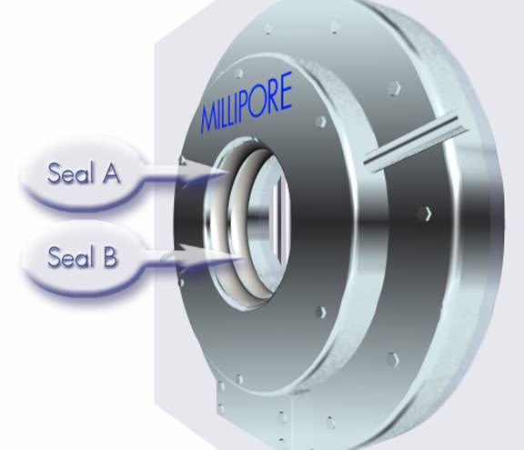
Figure 21: Location of Seals A and B, as seen from the Non-Sterile side of the Transfer Interface
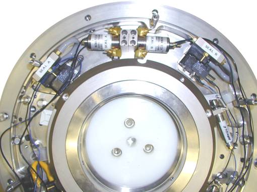
Figure 22: Transfer Interface with cover removed showing Seal Connections A and B
To replace the Seal Set a supervisor or qualified service personnel must perform the following steps:
Note: This procedure should be completed from the non-sterile side of the interface.
· Shut off power at the main cabinet.
· Remove the cover from the transfer interface.
· Disconnect the seal connection (white tube) from the actuators marked Seal A and Seal B.
· Remove Seal A from the transfer interface.
· Remove Seal B from the transfer interface.
· Install the new seal into the Seal B position (position closest to the sterile side).
Extremely Important: Verify that the flange on the seal is faced toward you during installation for both Seals A & B.
Figure 23: Seal unit showing orientation
· Plug in the seal connection to the actuator marked Seal B.
· Install the other new seal into the Seal A position (flange toward you).
· Plug in the seal connection to the actuator marked Seal A.
· Replace the cover back onto the transfer interface.
· Return power to the main cabinet.
· Turn on power to the system.
· Log on at supervisor level.
· Go to the maintenance screen.
· Touch the Seal # Icon.
· A screen is displayed with an alphanumeric keypad and a space for a seal number to be entered (the screen may be moved to the top or the bottom of the operator interface using the Ý or ß keys on the keypad).
· Enter the serial number assigned to the new seal set (it will be displayed in the Seal # window on the Access screen) and touch Enter. The Access screen will return.
· If the serial number is correct, touch the Press To Save Icon the batch number will be saved to a second Seal # window.
· If the serial number is incorrect, repeat steps 2 to 5.
Important: Each time the serial number is changed using steps 2 to 5 above the counter for Seal Set will reset to 10,000. This will also occur if the serial number is changed for a partially used Seal Set or a totally used Seal Set. The maximum recommended life of the Seal Set is 10,000 cycles. After this point the Seal Set must be changed to allow the system to function correctly.
The supervisor may at any time change operator and supervisor Access passwords. The following information associated with a password may be changed:
· Operators / Supervisors Name
· Access Level
· Password
To change this information the supervisor must undertake the following steps:
· Touch the Password Icon. A screen is displayed with an alphanumeric keypad.
· To enter a new operator or supervisor:
· Click on the box.
· Enter the Users name followed by the password and user level. Separate each item with a comma.
· Press escape.
· Press accept.
· To delete a user:
· Click on the box.
· Enter the name of the user you wish to delete.
· Press escape.
· Press accept.
L1 will allow the lamps to be switched On and Off as required. The default for L1 is off. When exiting the system the Icon should be returned to the default. The following steps should be followed when using this function:
· Touch L1. The lamps will activate.
· Touch L1. The lamps will deactivate.
SA will allow Seal A to be Inflated / Deflated as required. The default for SA is off. When exiting the system the Icon should be returned to the default. The following steps should be followed when using this function:
· Touch SA. Seal A will Inflate.
· Touch SA. Seal A will Deflate.
SB will allow Seal B to be Inflated / Deflated as required. The default for SB is off. When exiting the system the Icon should be returned to the default. The following steps should be followed when using this function:
· Touch SB. Seal B will Inflate.
· Touch SB. Seal B will Deflate.
DI will allow the Door Interlock to be switched On and Off as required. The default for DI is on. When exiting the system the Icon should be returned to the default. The following steps should be followed when using this function:
· Touch DI. Door Interlock will activate.
· Touch DI. Door Interlock will deactivate.
HI will allow the Handle Interlock to be switched On and Off as required. The default for HI is off. When exiting the system the Icon should be returned to the default. The following steps should be followed when using this function:
· Touch HI. Handle Interlock will activate.
· Touch HI. Handle Interlock will deactivate.
If an alarm condition arises during the operation of the Transfer Interface, an alarm will be activated and an alarm message will be displayed in the alarm window of the Operation screen.
Note: If the transfer Interface is in operation when the alarm even occurs, the transfer interface will automatically default to the Operation screen where the mimic panel and the alarm event is displayed.
If an alarm event is highlighted in the alarm window of the Operation screen, the alarm event must be cleared before the Transfer Interface will resume operation.
Important: If an alarm event occurs during a Sterilizing Cycle, the Sterile Transfer System PLC will automatically initiate the following DEFAULT FAILURE PROCEDURE to terminate the sterilizing sequence:
-Deactivate The UV Lamp Array
-Confirm Door Interlock Is Secure
-Release Vacuum
-Deflate Seal A
-Deflate Seal B
-Disengage The Docking Handle Interlock.
Important: When an alarm event(s) occurs resulting in the default failure procedure (as above), the Sterilizing Cycle that was being affected will be deducted from the total count available for that Sterilizing Source.
The following are the alarm events, which can occur for the Transfer Interface (grouped as noted):
|
Grouping |
Alarm # |
Alarm Event |
|
1. Docking Mechanism
|
1.01 1.02 1.03 1.04 1.05 1.06 1.07 1.08 1.09 1.10 1.11 |
Batch Number Not Entered Docking Handle Interlock Fault Door Latch Interlock Latch Fault Interface Collar Incorrect Position Door Not Open Door Seal A Did Not Inflate Door Seal B Did Not Inflate Door Seal A Did Not Deflate Door Seal B Did Not Deflate Compressed Air Failure Vacuum Failure |
|
2. Sterilizing Source |
2.01 2.02 2.03 2.04 2.05 2.06 2.07 2.08 2.09 2.10 2.11 2.12 2.13 2.14 2.15 2.16 2.17 2.18 |
UV Lamp #1 Fault UV Lamp #2 Fault UV Lamp #3 Fault UV Lamp #4 Fault UV Lamp #5 Fault UV Lamp #6 Fault UV Lamp #7 Fault UV Lamp # 8 Fault UV Lamp # 9 Fault Spare Sterilizing Source 25 Sterilizing Cycles Remaining Starter Set 100 Cycles Remaining Seal Set 100 Cycles Remaining Cycle Exceeded Fault Timer Sterile Source Has Reached Its Limit Starters Have Reached Their Limits Seals Have Reached Their Limits |
In the Alarm screen the operator can view the current alarm events. If an alarm occurs, an alarm message will be highlighted in the Operations screen alarm window. If the operator is in any other window at the time of the alarm, the Transfer Interface automatically defaults to the Operation screen. The operator can view the alarm in the alarm window and access the Alarm screen by touching the Alarm screen icon.
The operator must correct the alarm condition, and press the reset push button. The alarm will only be rendered “non-active”, after the fault has been corrected and the reset button has been pushed. Alarms, which have not reset, will have an “active” flag next to the alarm message. The list of “non-active” alarms can be cleared by pressing the [Clear Alarms] button on the touch screen.
The Programmable Logic Controllers used in the sterile transfer systems are Allen Bradley PLC’s Model # 1747_L532 CPU 5/03.
The development software used for the two sterile transfer systems is
STEP 7 – MICRO/WIN16 Version 1.2.
See the attached wiring diagrams.
Drawing MONS-SK-003.
Millipore Corporation (Millipore) warrants its products will meet their applicable published specifications when used in accordance with their applicable instructions for a period of one year from shipment of the products. MILLIPORE MAKES NO OTHER WARRANTY, EXPRESSED OR IMPLIED. THERE IS NO WARRANTY OF MERCHANTABILITY OR FITNESS FOR A PARTICULAR PURPOSE. The warranty provided herein and the data, specifications and descriptions of Millipore products appearing in Millipores published catalogues and product literature may not be altered except by express written agreement signed by an officer of Millipore. Representations, oral or written, which are inconsistent with this warranty or such publications are not authorized and if given, should not be relied upon.
In the event of a breach of the foregoing warranty, Millipores sole obligation shall be to repair or replace, at its option, the applicable product or part thereof, provided the customer notifies Millipore promptly of any such breach. If after exercising reasonable efforts, Millipore is unable to repair or replace the product or part, then Millipore shall refund to the customer all monies paid for such applicable product or part. MILLIPORE SHALL NOT BE LIABLE FOR CONSEQUENTIAL, INCIDENTAL, SPECIAL OR ANY OTHER INDIRECT DAMAGES RESULTING FROM ECONOMIC LOSS OR PROPERTY DAMAGE SUSTAINED BY ANY CUSTOMER FROM THE USE OF ITS PRODUCTS.
Millipore Corporation (Millipore) warrants Custom Order products against defects in materials and workmanship for a period of thirty (30) days following receipt by the purchaser. Millipore disclaims all other warranties whether express or implied, including the warranties of merchantability and of fitness for a particular purpose. Millipores sole obligation shall be to repair or replace, at its option, any Custom Order product that proves to be defective in materials or workmanship within the warranty period. Millipore shall in no event be liable for consequential damages for economic loss or property damage sustained from use of any Custom Order product.
Call, Fax or Write Millipore Customer Service.
Call: 1-800-MILLIPORE (1-800-645-5476)
(Monday-Friday, from 8 a.m. to 8 p.m.
Eastern Time)
Fax:
1-800-645-5439
Attention: Customer Service
Write:
Millipore Corporation
80 Ashby Road
Bedford, MA 01730
Attention: Customer Service
Call, Fax or Write Millipore International Customer Service
Call:
1-800-MILLIPORE, ext. 8622
(Monday-Friday, from 7 a.m. to 5 p.m.
Eastern Time)
Fax:
1-781-533-8630
Attention: International Customer Service
Write:
Millipore Corporation
80 Ashby Road
Bedford, MA 01730
Attention: International Customer Service
To Place an Order or to receive Technical Assistance or Additional Information, call your nearest Millipore office.
|
COUNTRY |
CONTACT |
ADDRESS |
TEL NUMBER |
FAX NUMBER |
|
AUSTRALIA |
Millipore Australia Pty. Ltd. |
9A Byfield Street North Ryde NSW 2113 |
Tel .1 800 222 111 (toll free) or (02) 9888 8999 |
Fax (02) 9878 0788 |
|
AUSTRIA |
Millipore Ges.m.b.H. |
Hietzinger Hauptstrasse 145 A-1130 Wien |
Tel. (01) 877-8926 |
Fax (01) 877-1654 |
|
BALTIC COUNTRIES |
Millipore Oy |
Ruukinkuja 4 FIN-02330 Espoo, Finland |
Tel. 358-9-804 5110 |
Fax 358-9-256 5660 |
|
BELGIUM AND LUXEMBOURG |
Millipore S.A.-N.V. |
Rue de la Fusée 60 Raketstraat 60 B-1130 Brussels |
Tel.+32 2 726 88 40 |
Fax+32 2 726 98 84 |
|
BRAZIL |
Millipore Indústria e Comércio Ltda. |
Rua Prof. Campos de Oliveira, 430 CEP 04675-100 Saõ Paulo-SP |
Tel.(011) 5548-7011 |
Fax (011) 5548-7923 |
|
CANADA |
Life Sciences Division: Millipore (Canada) Ltd. |
36 Antares Drive, Suite 280 Nepean, Ontario K2E 7W5 |
Tel.1-800-645-5476 |
Fax 1-800-645-5439 |
|
CANADA |
BioPharmaceutical Division: Millipore (Canada) Ltd. |
109 Woodbine Downs Blvd. Unit 5 Etobicoke, Ontario M9W 6YI |
Tel.1-800-645-5476 |
Fax 1-800-645-5439 |
|
CANADA |
Laboratory Water Division: Millipore (Canada) Ltd. |
19 Thorne St. Suite 302 Cambridge, Ontario N1R 1S3 |
Tel. 1-800-645-5476 |
Fax 1-800-645-5439 |
|
CHINA, PEOPLES REPUBLIC OF |
Millipore China Ltd. |
Suite 1209 China Resources Building 8 Jianguomembei Avenue Beijing 100005 |
Tel.(8610) 8519 1250 or (8610) 6518 1058 |
Fax (8610) 8519 1255 |
|
CHINA, PEOPLES REPUBLIC OF |
Millipore China Ltd. |
Suite 1303 Office Tower Citic Plaza 233 Tian He Bei Road Guangzhou 510620 |
Tel. (8620) 8755 4049 |
Fax. (8620) 8752 0172 |
|
CHINA, PEOPLES REPUBLIC OF |
Millipore Asia/China Ltd. |
Suite 3201 Central Plaza 18 Harbour Road Wanchai Hong Kong |
Tel. (852) 2803 9111 |
Fax (852) 2513 0313 |
|
CHINA, PEOPLES REPUBLIC OF |
Millipore China Ltd. |
Suite 901 Hong Kong Plaza (S) 283 Huai Hai Road (M) Shanghai 200021 |
Tel. (8621) 5306 9100 |
Fax (8621) 5306 0838 |
|
CZECH REPUBLIC |
Millipore spol. s.r.o. |
Ricanova 2116900 Praha 6 |
Tel.02-2051 3841 |
Fax 02-2051 4298 |
|
DENMARK |
Millipore A/S |
Odinsvej 9-19, st. 2600 Glostrup |
Tel.70 10 00 23 |
Fax 70 10 13 14 |
|
E. EUROPE, |
Analytical Division: Millipore S.A. |
BP 116 67124 Molsheim Cedex France |
Tel.+33 3 88 38 9536 |
Fax+33 3 88 38 9539 |
|
E. EUROPE, |
BioPharmaceutical Division: Millipore Ges.m.b.H. |
Hietzinger Hauptstrasse 145 A-1130 Wien, Austria |
Tel.+43 1 877-8926 |
Fax +43 1 877-1654 |
|
E. EUROPE, |
Laboratory Water Division: Millipore S.A. |
BP 307 78054 Saint-Quentin Yvelines Cedex, France |
Tel.+33 1 30 12 7000 |
Fax +33 1 30 12 7180 |
|
FINLAND |
Millipore Oy |
Ruukinkuja 4 02330 Espoo |
Tel. (09) 804 5110 |
Fax (09) 256 5660 |
|
FRANCE |
Millipore S.A. |
BP 307 78054 Saint-Quentin Yvelines, Cedex |
Tel. 01 30 12 7000 |
Fax 01 30 12 7180 |
|
GERMANY |
Millipore GmbH |
Hauptstraße 87 65760 Eschborn |
Tel. (06196) 494-0 |
Fax (06196) 43901 |
|
HUNGARY |
Millipore Kft. |
Budapest-1118 Ménesi út 23/a |
Tel.01-381-0433 01-381-0434 01-209-3232 |
Fax01-209-0295 |
|
INDIA |
Millipore (India) Pvt. Ltd. |
50A 2nd Phase Ring Road Peenya 560 058 Bangalore |
Tel.(91) 80-839 46 57 |
Fax(91) 80-839 63 45 |
|
IRELAND |
Life Sciences and Laboratory Water Divisions: Millipore (U.K.) Ltd. |
Units 3 & 5 The Courtyards Hatters Lane Watford, Hertfordshire, U.K. WD18 8YH |
Tel.+44 1923 816375 |
Fax+44 1923 818297 |
|
IRELAND |
BioPharmaceutical Division: Millipore Ireland B.V. |
Carrigtwohill, County Cork |
Tel.(021) 883 666 |
Fax(021) 883 048 |
|
ITALY |
Millipore S.p.A |
Via XI Febbraio, 99 20090 Vimodrone (Milano) |
Tel.(02) 25.07.81 |
Fax(02) 26.50.324 |
|
ITALY |
Millipore S.p.A. |
Via D. Sansotta 100 00144 Roma |
Tel.(06) 52.03.600 |
Fax(06) 52.95.735 |
|
JAPAN |
Nihon Millipore Ltd. |
Mita Kokusai Bldg. 4-28, Mita 1-Chome Minato-ku Tokyo 108 |
Tel.(03) 5442-9711 9736 Life Sciences 9737 BioPharm 9734 Lab Water |
Fax(03) 5442- |
|
KOREA |
Millipore Korea Co. Ltd. |
Suite 711 City Air Terminal Building 159-6, Samsung-Dong Kangnam-ku Seoul 135-728 |
Tel. (822) 551-0990 |
Fax (822) 551-0228 |
|
MALAYSIA |
Millipore Asia Ltd. |
Suite 3.03 Wisma KT No. 14 Jalan 19/1 46300 Petaling JayaSelangor |
Tel. 603-7571322 |
Fax 603-7571711 |
|
MEXICO |
Millipore S.A. de C.V. |
Ings. Militares 85-PB Col. Argentina Poniente 11230 México, D.F. |
Tel. (525) 576-9688 |
Fax (525) 576-8706 |
|
THE NETHERLANDS |
Millipore B.V. |
Penningweg 33 Postbus 166 4870 AD Etten-Leur (N.B.) |
Tel. 076-5022000 |
Fax 076-5022436 |
|
NORWAY |
Millipore AS |
Postboks 214 – Manglerud 0612 Oslo |
Tel. 22 67 82 53 |
Fax 22 66 04 60 |
|
POLAND |
Millipore Sp.z.o.o. |
ul. Jasnodworska 7 01745 Warszawa |
Tel. 22-669 12 25 22-663 70 31 |
Fax 22-663 70 33 |
|
PUERTO RICO |
Millipore Cidra Inc. |
P.O. Box 11977 Cidra, P.R. 00739-1977 |
Tel. (787) 273-8495 |
Fax (787) 747-6553 |
|
SINGAPORE |
Millipore Singapore Pte Ltd. |
31 Kaki Bukit Road 3 #06-08/11 Techlink Singapore 417818 |
Tel. (65) 842 1822 |
Fax (65) 842 4988 |
|
SPAIN AND PORTUGAL |
Millipore Iberica, S.A. |
Avda. Llano Castellano, 13-3° E-28034 Madrid, Spain |
Tel. +34 91 728 3960 |
Fax +34 91 729 2909 |
|
SWEDEN |
Millipore AB |
Box 7090 174 07 Sundbyberg |
Tel. 08-628 6960 |
Fax 08-628 6457 |
|
SWITZERLAND |
Millipore AG |
Chriesbaumstrasse 6 8604 Volketswil |
Tel. (01) 908-30-60 |
Fax (01) 908-30-80 |
|
TAIWAN |
Millipore Biosciences Asia Ltd. |
13th Floor, 160, Sec. 6 Min Chuan East Rd. Taipei, 114 |
Tel. 886-2-2792-9333 |
Fax 886-2-2792-6555 |
|
U.K |
Millipore (U.K.) Ltd. |
Units 3 & 5 The Courtyards Hatters Lane Watford, Hertfordshire WD18 8YH |
Tel. 01923 816375 |
Fax 01923 818297 |
|
U.S.A. |
Millipore Corporation |
80 Ashby Road Bedford, MA 01730-2271 |
Tel. (781) 533-6000 |
Fax (781) 533-3110 |
|
ALL OTHER COUNTRIES |
Millipore Intertech |
P.O. Box 255 Bedford, MA 01730 U.S.A. |
Tel.+1 (781) 533-8622 |
Fax +1 (781) 533-8630 |
M
MILLIPORE TECHNICAL SERVICE...................................................................................... 55
Millipore Web site............................................................................................................... 83
Millipore, contacting
Products Ordered in Countries Other Than the U.S.................................................................... 81
Products Ordered in the U.S. for Shipment Overseas.................................................................. 81
P
Parts
Spare Parts......................................................................................................................... 56
R
Repair................................................................................................................................. 89
S
SERVICE............................................................................................................................. 55
SPARE PARTS...................................................................................................................... 56
T
TECHNICAL SERVICE......................................................................................................... 55
W
Warranty............................................................................................................................ 76
Returning the Instrument to Millipore....................................................................................... 55
Figure 3: Interface Collar with cap and protective seal.
Figure 4: Sterile Transfer Container
Figure 5: Sterile Transfer Container
Figure 9: Removing the protective seal and overcap
Figure 10: Inserting the Interface collar into the docking port
Figure 11: Removing the Panel from the Interface Collar
Figure 17: Key parts of SafePass®(sterile side)
Figure 18: UV Source terms identification
Figure 19: Single Starter Unit with quick disconnect plug
Figure 20: View inside of Panel showing 7 Starter units properly configured
Figure 21: Location of Seals A and B, as seen from the Non-Sterile side of the Transfer Interface
Figure 22: Transfer Interface with cover removed showing Seal Connections A and B
Figure 23: Seal unit showing orientation
Table 1: Password Access Levels
Table 2: Spare Parts and Accessories